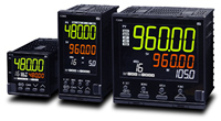
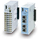
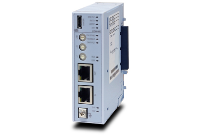
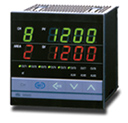
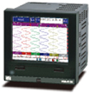
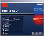
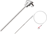
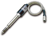
| Digital Indicator | ![]() |
| AG500 | |
| Specifications |
| Input | |||||||||||||||||||||||||
| Input type |
|
||||||||||||||||||||||||
| Measuring accuracy |
|
||||||||||||||||||||||||
| Cold junction temperature compensation error |
±1.0°C (Between 5 and 40°C) ±1.5°C (Between -10 and 5°C, Between 40 and 50°C) |
||||||||||||||||||||||||
| Sampling time | 0.25 sec | ||||||||||||||||||||||||
| Input impedance | a) DC High voltage : Approx 1MW b) Temperature, DC Low voltage : Approx More than 1MW c) DC Current : Approx 50W |
||||||||||||||||||||||||
| Sensor current | Approx 250mA (RTD input) | ||||||||||||||||||||||||
| Influence of external resistance |
Approx 0.2mV/W (Thermocouple input) | ||||||||||||||||||||||||
| Influence of lead resistance |
Approx 0.01%/W of Reading (Maximum 10W per wire) | ||||||||||||||||||||||||
| PV bias | -span to +span | ||||||||||||||||||||||||
| PV ratio | 0.500 to 1.500 | ||||||||||||||||||||||||
| Input digital filter | 0.1 to 100.0 sec. (OFF when 0 is set.) | ||||||||||||||||||||||||
| Input break action | a) Thermocouple input : Up scale/Down scale (Selectable) b) RTD input : Up sacale c) Low voltage input : Up scale/Down scale (Selectable) d) High voltage input : Value around 0V e) Current input : Value around 0mA |
||||||||||||||||||||||||
| Input short action | Down scale (RTD input) | ||||||||||||||||||||||||
| Hold function | |||||||||||||||||||||||||
| Peak hold | Highest measured value is held | ||||||||||||||||||||||||
| Bottom hold | Lowest measured value is held
|
||||||||||||||||||||||||
| Display | |||||||||||||||||||||||||
| Display digit | 5-digits (The most significant digit : -1 or 1) | ||||||||||||||||||||||||
| Flashing function | Flashing display at input error or event occurrence · Settable flashing function from each event 1 to 6. |
||||||||||||||||||||||||
| Alarm function (Optional) | |||||||||||||||||||||||||
| Number of alarms | Up to 6 points
|
||||||||||||||||||||||||
| Alarm type | Process High, Process low · Hold action is available. |
||||||||||||||||||||||||
| Alarm output | Relay contact output, Form a contact 250V AC 3A, 30V DC 1A (Resistive load) · Electric life : 300,000 cycles or more |
||||||||||||||||||||||||
| Differential gap | 0 to input span | ||||||||||||||||||||||||
| Delay timer | 0.0 to 600.0 sec | ||||||||||||||||||||||||
| Interlock (latch) function |
Interlock (latch) function is configurable. | ||||||||||||||||||||||||
| Energized/ de-energized action |
Energized/de-energized action is configurable. | ||||||||||||||||||||||||
| Digital Input (Optional) | |||||||||||||||||||||||||
| Nunber of inputs | 2 points (DI1 and DI2) | ||||||||||||||||||||||||
| Input method | Non-voltage contact input a) OPEN : 500kW or more b) CLOSE : 500W or less |
||||||||||||||||||||||||
| Determination time | 50 ms | ||||||||||||||||||||||||
| Function | a) DI1 : Hold reset b) DI2 : Alarm interlock reset |
||||||||||||||||||||||||
| Analog Retransmission Output (AO) (Optional) | |||||||||||||||||||||||||
| Output signal | a) 0 to 1V DC, 0 to 5V DC, 1 to 5V DC, 0 to 10V DC
|
||||||||||||||||||||||||
| Output type | Measured value (PV) | ||||||||||||||||||||||||
| Output accuracy | ±0.1% of span | ||||||||||||||||||||||||
| Output resolution | More than 12 bits | ||||||||||||||||||||||||
| Communication (Optional) | |||||||||||||||||||||||||
| Communication method |
RS-485 (2-wire), RS-422A (4-wire) | ||||||||||||||||||||||||
| Protocol | a) ANSI X3.28 sub-category 2.5A4 (RKC standard) b) MODBUS-RTU · Selectable |
||||||||||||||||||||||||
| Synchronous method |
Start-stop synchronous type | ||||||||||||||||||||||||
| Communitation speed |
1200bps, 2400bps, 4800bps, 9600bps, 19200bps, 38400bps | ||||||||||||||||||||||||
| Bit format | Start bit :1 Data bit : 7 or 8 (For MODBUS 8 bit only) Parity bit : 1 (odd or even) or none Stop bit : 1 or 2 |
||||||||||||||||||||||||
| Maximum connection |
31 units | ||||||||||||||||||||||||
| Communication data digits |
7 or 6 digits | ||||||||||||||||||||||||
| Sensor Power Supply (Optional) | |||||||||||||||||||||||||
| Output voltage | 24V DC ±1.2V or 12V DC ±1V | ||||||||||||||||||||||||
| Output current | 24V DC type : Less than 24mA DC 12V DC type : Less than 20mA DC |
||||||||||||||||||||||||
| Load resistance | 24V DC type : More than 1kW 12V DC type : More than 600W
|
||||||||||||||||||||||||
| General Specifications | |||||||||||||||||||||||||
| Waterproof/Dustproof | NEMA4X, IP66
|
||||||||||||||||||||||||
| Supply voltage | a) 90 to 264V AC (50/60Hz) Rating : 100 to 240V AC b) 21.6 to 26.4V AC (50/60Hz) Rating : 24V AC c) 21.6 to 26.4V DC Rating : 24V DC |
||||||||||||||||||||||||
| Power consumption |
|
||||||||||||||||||||||||
| Memory backup | Backed up by non-volatile memory (FRAM)
|
||||||||||||||||||||||||
| Insulation resistance | More than 20MW (500V DC) between measured terminals and ground More than 20MW (500V DC) between power terminals and ground More than 20MW (500V DC) between power terminals and measured terminals |
||||||||||||||||||||||||
| Dielectric voltage | 1500V AC for one minute between measured terminals and ground 1500V AC for one minute between power terminals and ground |
||||||||||||||||||||||||
| Power failure | A power failure of 20m sec or less will not affect the action. If power failure of more than 20m sec occurs, indicator will restart. | ||||||||||||||||||||||||
| Weight | Approx. 190g | ||||||||||||||||||||||||
| Ambient temperature | -10 to +50°C | ||||||||||||||||||||||||
| Ambient humidity | 5 to 95% RH (Non condensing) Absolute humidity : MAX. W.C 29g/m3 dry air at 101.3kPa |
||||||||||||||||||||||||
| Compliance with Standards | |||||||||||||||||||||||||
| CE Marking |
|
||||||||||||||||||||||||
| UL | UL 61010-1 | ||||||||||||||||||||||||
| C-UL | CAN/CSA-C22.2 No.61010-1 | ||||||||||||||||||||||||
| C-Tick mark | AS/NZS CISPR 11 (equivalent to EN55011) | ||||||||||||||||||||||||
| AG500 top page | Input range table | External Dimensions |
| Installation Manual >>> IMR02F06E1.pdf (345KB) | |
| Operation Manual >>> IMR02F07E2.pdf (410KB) | |
| Communication Instruction Manual >>> IMR02F08E2.pdf (275KB) |
| Corporate Profile | What's New! | Press Release | Products |
| Home Page |
| Exhibition | Job Opportunities | RoHS | Site Map |
| RKC INSTRUMENT INC. |